Fortifying Campus and Branch Networks: Proven Strategies for Always-On Connectivity
Have you ever noticed that service providers of all types (ISP's, CSP's, MSP's, etc.) will never offer an SLA (Service Level Agreement) of 100% uptime? You may see the common goal of "Five 9's" (99.999%), but no one can guarantee 100% uptime. Why? Because things fail…plain and simple. Operating systems crash, cables get cut, natural disasters happen, systems get overloaded, misconfigurations take place, bad actors are out there consistently trying to wreak havoc, and the list goes on and on.
In today's world, just about every organization is dependent on some sort of network connectivity for them to function, regardless of size or function. Outages can have a crippling effect on revenue, they can destroy confidence and reputations, and they can even put lives at risk in certain cases. For this reason, extreme measures are often taken to ensure uptime, such as:
- Dual WAN links (or more) with diverse paths, each using individual routers
- Server clusters with load balancers in strategic locations
- A/B power feeds that are both backed up by massive generators
- Geographically diverse backup sites for disaster recovery and business continuity
While these are common and typically effective actions taken within the WAN and data center, what about campus and branch networks? Do the same principles and methods apply? Since we are talking about mostly traditional two- and three-tier switching environments (yes, wireless is a major factor, yet the access points still connect to the switches), has anything even changed in the last 20 years? After all campus/branch networking is just a bunch of VLAN's and trunks, right?
Campus and Branch Resiliency
When designing a network, we typically divide this process into two key areas:
- Physical Design: The actual hardware components, their placement, and physical interconnections.
- Logical Design: focuses on how data flows, addressing, and the relationships between network elements independent of physical layout.
Physical Design
Redundancy within the Platform
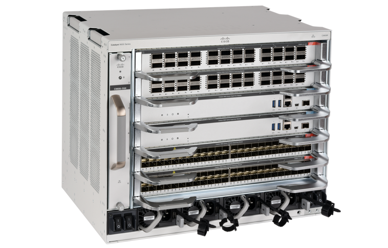
For critical devices within the campus/branch, the first aspect of resiliency starts with the platform itself—your physical network devices. In most cases, this involves modular systems designed with built-in safeguards, such as:
- Redundant Fans: Prevent overheating under heavy loads.
- Redundant Power Supplies: Ensure continued operation if one supply fails.
- Redundant Line Cards: Maintain traffic flow even if a card malfunctions.
- Redundant Supervisors: Minimize downtime by instantly failing over to a backup supervisor.
- Hot-Swappable Components: Allow parts to be replaced without fully powering down the system.
In the core and distribution/aggregation layers, network architects often use chassis-based switches to achieve robust platform resiliency.

Within the access layer, you can also opt for chassis-based switches. However, a more common alternative for boosting resiliency without the full cost or complexity of a chassis is a method referred to as "stacking", or "switch stacks." This is accomplished by interconnecting two or more fixed switches to form a single logical device with a unified control plane and shared configuration, which then provides:
- Simplified Management: Treat the entire stack as one switch instead of many.
- Redundancy: Even if one switch in the stack fails, the rest can continue forwarding traffic.
- Scalability: Easily add more switches to the stack as your network grows.
While stacking may not match the absolute redundancy of a full chassis system, it still offers a significant boost to platform resiliency—especially in environments where cost and rack space are key considerations.
Redundancy within the Topology
Moving on from the platform itself, we also have multiple ways to plan for continuity within the topology. A few of the most common methods for obtaining high availability include the following:
- Multi-Tiered Architecture: In a traditional setup (core, distribution, access), switches at the core and distribution layers are often deployed in pairs rather than as standalone devices.
- Multiple Interconnects: These paired devices typically have multiple cables (or interconnects) linking them together and connecting them to adjacent layers (e.g., uplinks to the core or downlinks to the access layer).
- Redundant Uplinks: Wherever possible, the access switches should also have redundant uplinks to eliminate single points of failure.
- Purpose of Redundancy: The extra devices and connections help ensure traffic can continue to flow if any single component—such as a cable, optic, or entire switch—goes down.
By carefully planning your physical layout, you reduce the likelihood of total network failure and help create a more resilient infrastructure.
Logical Design
While the physical design addresses the actual layout and how things are physically installed and connected, the logical design covers the flow of traffic within both the control plane and the data plane.
Control Plane
The control plane is responsible for determining how a device will forward data. This involves receiving forwarding information from nearby devices or control systems, installing it in forwarding tables, and sharing its own reachability information.
In order for the control plane to establish and utilize these channels of communication, a combination of Layer 2 (Data Link) and Layer 3 (Network) protocols must be used.
- Layer 2 protocols define how frames are formatted, forwarded, and kept loop-free on a local or directly connected network. They're essential for:
- Defining the basic link (Ethernet standards).
- Segmenting and trunking traffic (VLANs, 802.1Q, QinQ).
- Preventing loops and ensuring redundancy (Spanning Tree protocols, REP).
- Aggregating bandwidth and connections (LACP, PAgP).
- Discovery and topology management (CDP, LLDP).
- Layer 3 protocols define how packets are routed and delivered across multiple networks. They're essential for:
- Addressing and Forwarding: Using IP (IPv4 or IPv6) to identify devices and route packets across local and wide-area networks.
- Best Path Selection: Employing dynamic routing protocols (e.g., OSPF, EIGRP, BGP, IS-IS) to discover and choose optimal paths.
- Network Segmentation: Splitting large IP address spaces into smaller subnets for efficient traffic management and isolation.
- Tunneling and Security: Providing secure, encapsulated connections (e.g., GRE, IPsec) for remote access, site-to-site VPNs, or overlay networks.
- Scalability and Reliability: Leveraging route summarization, multi-homing, and fast convergence features to handle growth and failover needs effectively.
Methods for Control Plane Resiliency
Control plane resiliency ensures that routing, switching, and network management processes remain stable and available, even in the face of failures. Below are some key methods to achieve control plane redundancy:
- Multi-Homing: Connect to multiple upstream ISPs or edge routers so that external routes aren't lost if a single link or device goes down.
- Dual Supervisors in Chassis Switches: In many chassis-based switches, you can have two supervisor modules where one is active and the other is in hot-standby mode. If the active supervisor fails, the standby immediately takes over.
- Stacked or Clustered Switches: Switch stacking (e.g., Cisco StackWise, Aruba VSF) or clustering (e.g., Cisco StackWise Virtual, Juniper Virtual Chassis) can maintain a single, unified control plane across multiple physical switches for better redundancy and simplified management.
- Hierarchical Design with Summarization: Summarize routes at distribution or aggregation layers, which stabilizes the control plane by minimizing recalculation in the core if access-layer devices go offline.
Data Plane
The data plane is responsible for receiving, processing, and forwarding actual traffic based on instructions from the control plane. This includes forwarding packets or frames to the correct output interface as well as applying services such as access lists, encryption, or traffic shaping in real time.
Methods for Data Plane Resiliency
Data plane resiliency ensures that traffic forwarding continues seamlessly even if links, devices, or interfaces fail. Below are key methods and technologies used to maintain high availability within the data plane:
MLAG (Multi-Chassis Link Aggregation Group)
MALG is a technology that allows you to bond network links across two or more physical switches, making them appear as a single logical switch to downstream devices. This setup provides redundancy and active-active forwarding without needing to rely solely on Spanning Tree Protocol (STP) for loop prevention.
How MLAG Works
- Traditional LAG: Normally, link aggregation happens between one switch and another (e.g., LACP bundles multiple ports on each side).
- MLAG: With MLAG, you connect two physical switches on the "upstream" side to a single device (server, switch, or router) on the "downstream" side. The downstream device sees a single logical switch, even though there are actually two.
Below are the MLAG (Multi-Chassis Link Aggregation) solutions used by Cisco, Aruba, Juniper, and Arista:
Cisco
- vPC (Virtual Port Channel) – Used on Nexus switches.
- StackWise Virtual – Used on Catalyst 9000 series switches (a successor to VSS).
HPE Aruba
- VSX (Virtual Switching Extension) – Used on Aruba CX switches.
Juniper
- MC-LAG (Multi-Chassis Link Aggregation Group) – Juniper's MLAG solution for data center and enterprise switches.
- Virtual Chassis – Allows multiple switches to operate as a single logical unit but differs from traditional MLAG.
Arista
- MLAG (Multi-Chassis Link Aggregation) – Arista simply refers to its implementation as MLAG without a unique marketing term.
Equal-Cost Multi-Path (ECMP)
ECMP is another important concept that intersects both control plane and data plane resiliency. In essence, ECMP allows multiple next-hop paths to have the same cost within the routing table. As a result, the router (or switch) can load-balance traffic across these equal-cost paths and continues forwarding without the need for reconvergence if one link fails.
Here's how ECMP contributes to control plane and data plane redundancy:
Control Plane Perspective
- Protocol-Supported: Most modern routing protocols (like OSPF, EIGRP, BGP) will advertise multiple equal-cost paths in the routing table.
- Redundant Path Knowledge: The control plane calculates multiple next hops, so if one link or router goes down, the control plane quickly converges to the other equal-cost path(s).
Data Plane Perspective
- Load Balancing: In many implementations, the data plane uses a hash-based approach to distribute traffic across the available links.
- Rapid Failover: If one link fails, the data plane seamlessly reroutes traffic onto the remaining path(s) without requiring a full reconvergence event, reducing downtime.
Key Benefits
- Increased Bandwidth: Bundling multiple equal-cost routes can effectively aggregate capacity.
- Improved Resiliency: If one path fails, traffic can immediately switch to the remaining paths.
- Scalability: ECMP is often easier to scale than some other forms of redundancy because adding more equal-cost paths can be incremental and non-disruptive.
Where ECMP is Typically Utilized in the Campus
- Routed Access: When all connections from core to access are L3 and the gateways for each VLAN reside on the access switches.
- L3 Core/L2 Distribution: When the gateways reside at the distribution/aggregation with MLAG down to the access switches and ECMP between the distribution/aggregation and core layers.
- Campus Fabric: When an underlay/overlay deployment exists, ECMP is utilized for the underlay and the overlay allows for Anycast Gateways on the access switches
ESI LAG (Ethernet Segment Identifier - Link Aggregation Group)
ESI LAG is a redundant multi-chassis link aggregation technology primarily used in EVPN (Ethernet VPN) environments. It extends traditional MLAG (Multi-Chassis Link Aggregation) by integrating EVPN control-plane signaling, making it more scalable and flexible. This was traditionally deployed in modern data center and service provider networks, but we now have this in the campus as well
How ESI LAG Works
- Ethernet Segment Identifier (ESI):
- Each multi-homed Ethernet segment (LAG across multiple switches) is assigned a unique identifier called an ESI (Ethernet Segment Identifier).
- This allows devices in an EVPN fabric to identify and load-balance traffic across multiple switches without loops.
- EVPN Control Plane (BGP-Based):
- Unlike traditional MLAG, which relies on proprietary peer links, ESI LAG uses EVPN Type 1 and Type 2 routes in BGP to signal reachability and synchronize MAC addresses.
- This eliminates the need for a direct peer link between MLAG switches.
- Active-Active Redundancy:
- Allows dual-homing of endpoints (e.g., servers, firewalls, routers) to two or more switches while ensuring loop prevention and seamless failover.
- Traffic load-balancing is done at Layer 2 without relying on Spanning Tree Protocol (STP).
- Automatic Failover and Split Brain Prevention:
- If one switch in the ESI LAG pair fails, EVPN signaling ensures that traffic is rerouted to the surviving switch.
- Unlike traditional MLAG, no dedicated peer-link is required, reducing operational complexity.
Centralized Management and Orchestration
Centralized management and orchestration in a campus network involves using a single control system to configure, monitor, automate, and optimize operations across multiple network devices. This approach reduces complexity, increases efficiency, and enhances security by eliminating manual device-by-device configuration. The primary examples include the following:
- Cisco: Cisco Catalyst Center (for automation, analytics, and security integration)
- HPE Aruba: Aruba Central (cloud-based management for wired and wireless networks)
- Juniper: Mist AI (AI-driven network automation and security insights)
- Arista: CloudVision (multi-domain orchestration and telemetry platform)
Key Aspects of Centralized Management & Orchestration
- Centralized Configuration & Automation
- Automated Provisioning – Configure new devices or update existing devices instantly by pushing templates from a central controller.
- Consistent Configurations – Eliminate snowflake configurations and allows for standardization at scale
- Zero-Touch Deployment (ZTP) – Enables plug-and-play setup for new switches, routers, and access points.
- Network Monitoring & Analytics
- Real-Time Visibility – Provides a single dashboard to monitor traffic, device health, and user activity across the entire network.
- AI-Driven Insights – Uses machine learning to detect anomalies, predict failures, and optimize network performance.
- Event Correlation & Alerting – Identifies patterns in network issues and provides automated recommendations.
- Automated Orchestration & Troubleshooting
- Intent-Based Networking (IBN) – Allows admins to define network policies in plain language, with the system handling implementation.
- Self-Healing Networks – AI and automation can proactively identify and fix network issues before they cause downtime.
- Security & Access Control Integration
- Network Access Control (NAC) – Integrated with management platform for centralized authentication and authorization for all users and devices.
- Segmentation & Microsegmentation – Provides the vehicle to automate the dynamic isolation of devices and users to prevent lateral movement of threats.
- Automated Threat Response – Uses AI-driven security analytics to detect and respond to potential attacks.
How Centralized Management & Orchestration Contribute to Uptime in the Campus
- Guided Remediations - The platform can help pinpoint specific issues as they arise and provide recommendations to resolve them.
- Dynamic Baselining with RCA - The platform can learn what is normal behavior within the network and identify when deviations occur. Rather than spending days or weeks to determine root cause after an issue, these deviations can be analyzed through machine learning and point out the likely culprit within minutes.
- Removing Human Error - A human will still manage the platform, but he or she will not apply configurations directly to devices, drastically reducing the potential for a misconfiguration.
- Proactive Troubleshooting and Maintenance - Potential issues can be identified and brought to your attention before they become problems, so you can address them proactively rather than reactively.
- Intent-Based Networking - Engineers can focus on "what" they want the network to do rather than "how" to accomplish it and the platform can create the configurations and provision them to the devices.
Conclusion: Achieving Always-On Networking in the Campus
Ensuring always-on connectivity in campus and branch networks requires a multi-layered approach that incorporates redundancy, resiliency, automation, and intelligent management. As we've explored, achieving high availability isn't just about adding more hardware—it requires carefully designed redundancy at the platform, topology, control plane, and data plane levels to minimize points of failure and allow seamless failover.
Additionally, centralized management and orchestration platforms have transformed network operations, shifting from reactive troubleshooting to proactive, AI-driven optimizations. By removing human error, dynamically analyzing network baselines, and automating remediation, these platforms enable IT teams to keep campus networks operational 24/7, even in the face of hardware failures, misconfigurations, or cyber threats.
Ultimately, modern campus networks must be built with resiliency in mind—leveraging redundant architectures, intelligent failover mechanisms, and automated management to create a self-healing, highly available infrastructure. By adopting these best practices, organizations can ensure that their networks remain fast, secure, and uninterrupted, no matter what challenges arise.works remain fast, secure, and uninterrupted, no matter what challenges arise.